
It's winter, and as usually happens in winter, I'm having a hard time opening the gate to our back yard. Why? It's not the snow, it's physics.
We have a standing policy that as much as possible, Emmy goes in and out through the back door for walks and small-animal-chasing in the backyard. This has occasionally been lifted, when a tree limb fell on our back gate, and when they were building the deck, but for the most part, when we had to go in and out through the front door, but she mostly knows not to go charging out the front door, which is the whole point.
Access to our fenced back yard is through a fairly wide gate consisting of most of one panel of the 6-foot stockade fence we have in the back (the front corner of the yard has 4' fence, because of Town of Niskayuna requirements, but the bit where the gate is is allowed to be taller). This is, as you might imagine, kind of heavy, and we have a persistent problem with the gate sagging down to drag on the ground. This is particularly pronounced in the winter, when snow and frost heave raise the level of the path, and snow and ice weigh down the gate, so opening the gate now involves hauling it up a bit in order to be able to push it open about 1/3rd of the way until it hits the ground and won't move any farther.
The root cause of this is classical physics, as is the likely solution. Which I will attempt to explain here, using this diagram:
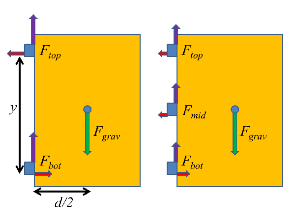 Diagrams representing the two- and three-hinge configurations for hanging the gate to our back yard.
On the left in the figure, you see the current configuration of the gate: a large wooden panel supported by two hinges on one side. So, what are the forces that act, here? Well, this is a resolutely classical kind of system, so we have three forces that can act: the weight of the gate, due to the gravitational attraction of the Earth, represented by the green arrow labeled "Fgrav" in the figure, and two contact forces from the hinges.
Now, about two weeks into first-year Newtonian mechanics, any physics student should be able to say that since the gate isn't moving, these must sum to zero:
$latex \vec{F}_{grav} + \vec{F}_{top} + \vec{F}_{bot} = 0 $
Since gravity by definition pulls straight down, and only straight down, this means that the two hinge forces must have vertical components indicated by the purple arrows at the left.
That's not terribly interesting or useful by itself, though. You need to get toward the end of the term before you learn what really matters here, namely the torque. The force of gravity acts on the center of mass of the gate, but the hinges act on the left edge. The distance between these means that while the net force on the gate is zero, the gate will have a tendency to rotate. And that's the source of the problem-- gravity wants to make the gate rotate in a clockwise manner, which brings the right edge down into the ground, and the hinges need to stop it.
To understand rotation, we need to think about torque, which combines force with the distance from the axis of rotation. The rotation point in this case is the lower hinge, more or less, in which case the torque due to gravity is given by:
$latex |\tau_{grav}| = F_{grav} (d/2) $
where d/2 is half the width of the gate (assuming a uniform density rectangle, blah, blah, blah). This might seem too simple, because formally you would calculate the full distance from the hinge to the center of mass and then take a vector product, but there's a convenient shortcut, namely using the full force and the perpendicular distance to the line along which the force acts; it saves doing a bunch of trigonometry.
Stopping this rotation must require an equal and opposite torque from the hinges. Now, if we're taking the lower hinge as the rotation axis, it can't exert any torque, which means everything has to come from the top hinge. And that, in turn, means that there must be a horizontal component to the top hinge force, acting to the left, whose magnitude we can find from setting the torques equal:
$latex F_{top,x} y = F_{grav} d/2 $
(where y is the distance between hinges, which is not quite the full height of the gate).
Of course, adding a leftward force on the top hinge would cause the whole gate to move to the left unless it's balanced by a rightward force from something, which in this case must be the bottom hinge. So, to stop the rotation, we have the top hinge pulling left, and the bottom hinge pushing right. And the additional stress this puts on the hinges is what causes the dragging problem-- when I look closely at the gate, the top hinge is clearly stretched somewhat to the right, and the bottom hinge is compressed to the left, exactly as you expect from physics. The hinges deform a little, and the gate rotates a little until the ground pushing up on the lower right corner provides the additional torque needed.
So, what to do about this? Well, the quick and easy solution is just to add a third hinge, as shown on the right (aligning the three hinges with the three horizontal rails on the stockade fense we're using for a gate). You still have the same basic situation-- gravitational and hinge forces acting some distance apart-- but adding the third hinge will reduce the forces on the other two. The basic force equation thus becomes:
$latex \vec{F}_{grav} + \vec{F}_{top} + \vec{F}_{bot} +\vec{F}_{mid} = 0 $
and the torque equation becomes:
$latex F_{top,x} y + F_{mid,x} y/2 = F_{grav} d/2 $
As long as Fmid is greater than zero, this has to reduce the total force on the upper hinge, making it less likely to deform enough to drag the right edge of the gate on the ground.
Of course, hanging a big heavy gate with two hinges is kind of annoying, and adding a third hinge is going to be more annoying yet. Which is probably why the guys who fixed it the last time didn't add the third hinge, despite my specifically suggesting that they should do that. But the physics of the situation is pretty clear, so once it warms up enough to melt the snow by the gate, I'll recruit some neighbors to help with lifting it into place, and fix the damn thing myself.
- Log in to post comments
Your explanation seems sound, but I'm puzzled by your comment that this problem occurs in winter, but your explanation does not seem to hinge on that.
More practically -- rather than rehanging the gate you could consider putting a wheel under the gate to support it and allow for easier motion.
Your explanation seems sound, but I’m puzzled by your comment that this problem occurs in winter, but your explanation does not seem to hinge on that.
I see what you did there...
The problem gets worse in the winter for two reasons: one, that the effective ground level rises due to snow and frost heave, and two, the extra weight of snow and ice clinging to the gate makes the bending problem worse. And, of course, we tend to fix it in warm weather, so there's also a simple elapsed time issue-- the hinges deform slowly, so by the time winter rolls around and the ground comes up, they've bent enough to be a bigger problem.
I have a similar problem, although its not ground clearance, but rubbing against latch area on the righthand side. Its worse in winter because of swelling due to humidity. Over time IMO the torque on the hinge post causes it to creep rotate clockwise. I've added some bungie cord tension from the top of the post downwards and leftwards to try to counteract this torque on the post.
Nice explanation. I need to memorize the explanation as this sort of thing comes up a lot.
A neat little trick to get a gate that won't sag for a very long time is to mount the gate on as many hinges as necessary, then swing it close and screw a block of wood tight underneath the latch side of the door using two thicknesses of plastic or phosphor-bronze strip between the block and bottom of the gate. Open the gate and very slightly bevel the block and contact surface under the gate and wrap and nail the plastic or metal in place in a manner that keeps the nails out of the contact area.
What you end up with a the latch side of the gate being supported by the block when the gate is closed. Being closed most of the time this goes a long way toward eliminating sagging. The plastic or metal is there to keep the top of the support block from rotting and to limit friction so dragging the gate off the block doesn't take much effort.
Is the gate still square? Assuming it's made with rails and stiles, gravity is going to pull it out of square into a parallelogram. and because wood shrinks in winter, the sagging will be much more pronounced.
I recommend talking to one of your no-longer-freshman students who has had a couple of years of engineering classes. You are dealing with a deformable object, something rarely addressed in any physics class you or I have ever had, that has some indeterminant aspects to it we ignore in standard HW problems like you pictured above. (What system of equations did you solve to get the ratio of top = mid = bot/2 for the horizontal forces in the 3-hinge problem or, for that matter, that the vertical forces are equal on the 2-hinge problem?)
On a more practical level:
First, the usual solution starts with a diagonal brace across the panel, usually a cable tensioned with a screw-type comealong that will keep the panel square. A diagonal wood brace is unlikely to deal with the loads on something of the size you describe as per comment #5. I would do this along with the suggestion in #4, and recommend adding a kick plate above the slide since it will surely ice up in the winter.
Second, is the top hinge permanently bent and/or pulling out of the post, elastically deformed, or just moving within the slop allowed by the hinge itself? The first two require a better hinge because they indicate the problem is not just with the sag of the wooden structure.
Third, if the top hinge is inelastically deforming (hence pushing its failure limit) and you can't get stronger hinges, you might add a second hinge up at the top where it will more equally share the load with the other (i.e. if one starts to deform because it has too much of the load due to tiny misalignments, the load will shift to the other until things come into balance). Putting the extra one in the middle requires more force (and more deformation) to supply the same torque. It will look better in the middle, and might be enough to solve the problem, but the top hinge will still want to fail.
A typical hinge is not designed to withstand a significant side force. You probably can ask someone who do metal work to make a more robust one, with both ends of the rod fixed.
The gate is not dramatically deformed from its original basically-square shape, because it has some added cross-braces that specifically prevent that (at the cost of extra weight...). The sag we see is due to permanent deformation of the two hinges, which are visibly bent out at the top and in at the bottom.
I agree that doubling the hinges at the extreme points would work better from the standpoint of reducing the forces on the hinge, but adding a third hinge in the middle is the practical compromise forced by the stockade fence construction. The only solid way to anchor the hinges to the gate is along the horizontal wooden rails that hold the vertical slats in place, and those are too narrow to take two hinges in parallel. There are, however, three horizontal rails, only two of which are currently in use, so a third hinge it is.
The latch-side support is also a good idea, and I'll see if I can get that to work. I worry a bit about the frost-heave problem, though, as some of what we see is the ground rising up when it freezes (the latch side is now clear of the ground when the gate is closed, for example, because the ground has subsided a bit in the warm weather we've had the last week).
You already have the perfect physics gate, so leave out that third hinge. My students (and the custodians) always wondered why I removed the middle hinge from the classroom door. Then, when we got to talking about torque, the demonstration was ready to go, with a little hammer and punch for the hinge pins. We also had the discussion about where to not put your fingers when the hinge pin came out.
#10 reminds me that some sort of bearing surface (like bridge beams rest on) just below the bottom hinge would keep it from collapsing. You don't need a hinge there except for alignment. Adding the idea from #4 below the latch might solve the problem of too-weak hinges.
My observation is that if the lower hinge is collapsing as you describe, adding a middle hinge might not change anything without those other changes. It might still rotate around the "mid" axis just as it is doing now (until the lower hinge starts to bottom out and the mid hinge goes to work).
Remember, the rigid body equations for the problem you have diagrammed have to have net zero torque about any point, including the "mid" axis, whether there is a hinge there or not. Adding the hinge allows solutions where Ftop,x is not -Fbot,x -- because Fmid,x is not zero -- but you can still have a solution where Fmid,x is zero. Fmid,x can be anything at all for a rigid gate. The equations are indeterminant. You need to include the deformation of the gate to solve for them.
I'll repeat my recommendation that you track down one or two of your better students from a year or two ago and see what they have learned in the meantime as engineering majors. They might even be able to use your gate as a design project in a junior-level strength of materials course, one where non-rigid bodies come into play. Those kinds of indeterminant problems are very messy. They will know when you can make simplifying assumptions and when you cannot.