
Last week, we looked at the resistance of a voltage sensor by using the discharge of a capacitor, getting a value that was a bit high, but not wildly out of line with the specs. This time out, we're going to look at the resistance of a current meter, because some students asked about it during Wednesday's exam review session.
The question came up because one of the things I have on the standards for the circuit portion of the class is knowing how to hook up a current meter and a voltage meter in the appropriate ways. This is strangely confusing for a lot of students, which gets annoying, as hooking them up wrong leads to blown fuses in the meters, and the fuses are a pain in the ass to change. So I made it one of the items to be assessed, in hopes that would provide some incentive to get it right.
One of the useful facts I mentioned that can help students remember the correct connection is that current meters ideally have very low resistance, so as not to perturb the current flowing through the circuit (voltage meters, on the other hand, have very high resistance, so as to prevent current from flowing, and keep from perturbing the voltages). One of the students noted that real meters must have some finite resistance, and I mentioned last week's silly experiment. Whereupon it occurred to me that I could also measure the resistance of a current meter, to confirm that it is, indeed, small.
The method here is dead simple, and used the highly sophisticated apparatus shown above. I set up a DC power supply producing 10V in series with a 470Ω resistor, to provide a small amount of current. Then I added as many identical current meters as I could round up, which turned out to be eight of the Instek GDM 396 multimeters on the milli-amp setting. Each time I added a meter, I recorded the current on all of the meters in the circuit, producing the following graph:
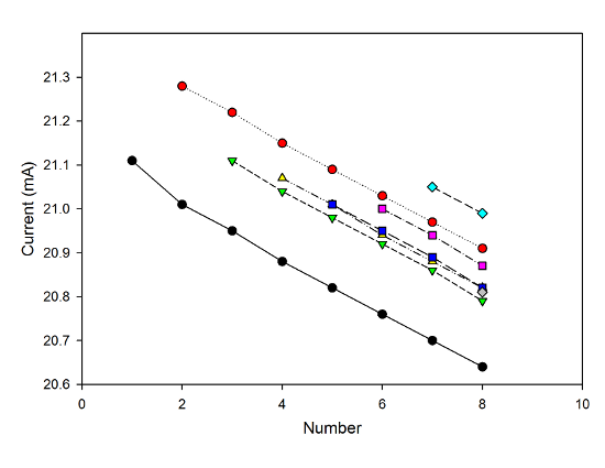 The current vs. the number of meters, as measured by each of the eight meters used.
You can see that there's a bit of scatter in the readings, some showing slightly higher values, and other slightly lower. I attribute this to the calibration of the meters-- the total difference between the highest and lowest readings with all eight in the circuit is under 2% of the current being measured. You can also clearly see a trend: as the number of meters increases, the current decreases. All of the meters for which there are enough readings to show a trend show the same downward trend, decreasing by about the same amount each time.
These current readings are easily converted to resistances for each step. Then, just because overkill is fun, I did a linear fit to the data for each meter (well, for each of the six that had more than two points) to find the resistance change per meter:
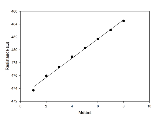 Resistance data with a best-fit line.
(That graph is for the data from the first meter in the chain, which provides the most points; I did fits for all six of the meters with three or more measurements, but only made the one graph, because I'm lazy.)
Putting those measurements together gives a resistance for a single meter of 1.45±0.02 Ω. Which is, indeed, a small resistance, given that the lowest resistance you usually work with in real circuits is around 50Ω. Instek doesn't offer a spec for this, so I can't compare to the "official" value. This doesn't seem unreasonable, though.
Now, you might be thinking that this is a needlessly complicated way of doing things-- after all, a single meter produces a measurable change in the current, so why not just use that? Or, for that matter, take the second meter, set it to measure resistance, and put it across the terminals of the first one, then use that number?
For one thing, doing just a single measurement wouldn't be very much fun. But more than that, there are a couple of benefits to doing this more complicated procedure. The main benefit is that chaining several meters together gives a total resistance that's much larger than the value for a single meter. The uncertainty in a given measurement is usually some percentage of the value being measured-- Instek claims a couple of percent of the current for these meters-- so if you're trying to measure a change in some value, you want to make that change as large as possible to be sure that your measurement is bigger than the uncertainty. If you take the spread in current measurements as indicative of the uncertainty, even all seven extra meters barely get to that point.
But if you're going to chain a bunch of things together, you may as well also measure each step. This provides a useful sanity check to make sure there isn't something wacky going on with the meters-- the trend is clearly linear, showing that each one has about the same resistance. And combining a bunch of measurements together can give you an overall uncertainty that's lower than you would get from a single measurement. Or even from measuring each of the resistances individually and averaging those.
Now, that's not really essential for something silly like this, but if you were doing a real measurement of something of genuine physical interest, you'd be better served by measuring trends than just recording a single value and calling it a day.
And that's this week's episode of "Overthinking simple problems in introductory physics..."
For the record, if I plug one meter into another using the resistance setting, it says the resistance of the current meter is 1.2 ohms.
Chad,how would you build an Irony Meter that can withstand 11 Hams or 22,000 Egnors ?
Can you use a hunt ?
An irony overload shunt ?
The 1.45 Ohm reading includes some contact potential from the lest lead plugs and the sockets on the meters. The wire leads also contribute some R. Leads are usually 18ga, which is 6 mOhms/foot, so basically negligible.
You'd be surprised how many techs don't know the operating principles of their tools. You can tell which ones because they'll measure voltage without switching out of the current setting. Poof.
A few questions:
Why didn't you ask the students to design this experiment?
Why is one of the meters hooked up wrong in your picture?
Don't you dock them a point for blowing a fuse?
Why didn’t you ask the students to design this experiment?
It was an exam review session, and their heads would've exploded.
Why is one of the meters hooked up wrong in your picture?
I had disconnected one to do a direct resistance measurement, and hastily reconnected it to take the picture.
Don’t you dock them a point for blowing a fuse?
I jokingly threaten to add the cost to their tuition bill.
I mention that because I have learned that students will go to great lengths to earn or avoid losing even a nanopoint. The only reason I don't is it would require editting my syllabus.
But I do remind them that one toasted meter DID come out of their collective tuition.